Placing redlines
|
Tool |
Tool set |
|
Redline
|
Dims/Notes |

Use the Redline tool to create redline objects, which are graphical time-stamped change requests on the drawing.
![]()
|
Mode |
Description |
|
Oval
|
Inserts the redline with an oval shape. Click to set the start point, move the cursor to preview the desired shape, and click again to create the object. |
|
Rectangular
|
Inserts the redline with a rectangular shape. Click to set the start point, move the cursor to preview the desired shape, and click again to create the object. |
|
Regular Polygon
|
Inserts the redline with a regular polygon shape. Click to set the start point (first vertex), click at the desired location for each subsequent vertex, and either click at the starting vertex to close the polygon or double-click at the final vertex to create an open polygon. If the polygon is open, the shape is completed based on the outline. |
|
Freehand Polygon
|
Inserts the redline with a freehand polygon shape. Click to set the start point and click-drag to draw the freehand polygon. If the polygon is open, the shape is completed based on the outline. |
|
Preferences
|
Sets the default parameters for the tool |


To redline an object or area:
Click the tool and mode.
Click Preferences to open the Place Redline dialog box and specify the tool’s default parameters. The parameters can be edited later from the Object Info palette.
Click to show/hide the parameters.Click to show/hide the parameters.
|
Parameter |
Description |
|
Redline Style |
Select the style to apply to the redline object: Cloud: Applies a cloud style. Radius: Applies corner smoothing with a solid line style. Radius Dashed: Applies corner smoothing with a dashed line style. Simple: Applies a simple solid line with no smoothing. Simple Dashed: Applies a simple dashed line with no smoothing. |
|
Authorized By |
Specifies the default name or initials of the person who authorized the change; this name is used for the redlines created in this file |
|
Assigned To |
Specifies the default name or initials of the person who has been assigned the task; this name is used for the redlines created in this file |
On the design layer where the revision is to be performed, draw the redline around the revision area.
Based on the selected creation method, the appropriate tool creates the redline. This allows the use of SmartCursor cues, object snapping, and boomerang mode when drawing redlines.
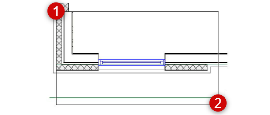
Rectangular mode depicted
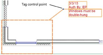
The Place Redline dialog box opens. Enter the redline information and authorization.
Click to show/hide the parameters.Click to show/hide the parameters.
|
Parameter |
Description |
|
Redline Notation |
Enter text describing the redline condition (and/or specifying the recommended action) |
|
Authorized By |
The file’s default Authorized By setting is displayed, but it can be changed for this redline instance |
|
Assigned To |
The file’s default Assigned To setting is displayed, but it can be changed for this redline instance |
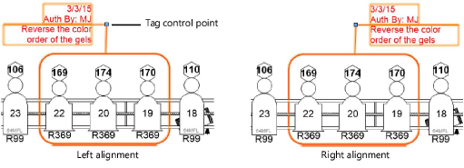
The redline object indicates the current date and the drawing condition to be corrected. Position redline text by clicking on the tag control point and dragging the tag to the desired location. If there are several redline objects, use the Align/Distribute Leader Lines command to improve readability (see Aligning and distributing leader lines).
The parameters of one or more selected redline objects can be edited later from the Object Info palette.
Click to show/hide the parameters.Click to show/hide the parameters.
|
Parameter |
Description |
|
Rotation |
Specifies the number of degrees to rotate the object (0.00 is horizontal) |
|
Text Style |
Select a text style from a library or the current file. To use the style defined for the object’s class, select <Class Text Style>. To format the text using options on the Text menu, select <Un-Styled>. See Using text styles and Formatting text. |
|
Redline Style |
Select a redline style from the list |
|
Tag Alignment |
Specifies the alignment of the redline tag: Auto: Justifies the text away from the center of the redline object. Left: Places the text to the left of the tag control point and right-justifies the text. Right: Places the text to the right of the tag control point and left-justifies the text.
|
|
Picked Up |
Selecting Picked Up indicates that the redline has been resolved or “picked up.” The redline color changes to yellow and the pick-up date is automatically assigned. Deselect to indicate that a previously resolved redline has been restored. |
|
Show Authorizer |
Displays the Authorized By information on the redline |
|
Authorized By |
Enter the initials or name of the person authorizing the change |
|
Show Assignee |
Displays the Assigned To information on the redline |
|
Assigned To |
Enter the initials or name of the person assigned to correct the condition |
|
Creation Date |
The redline creation date is displayed |
|
Pick Up Date |
The redline pick-up date is displayed |
|
Notation |
Redline comment information is displayed and can be changed |
|
Tag Length |
Controls the length of the line separating the redline comments from the redline information, and changes the redline comment text wrapping |